At 10 MHz, a 50 Ω source driving a 300 Ω load via a low-pass L-pad transformer requires a capacitance of 118.62 pF and an inductance of 1.779 μH. Previously it was shown that using the lossy resistive impedance transformer, the attenuation would be 5.63 dB into a 300 Ω.
\(\hspace{18.9cm}\)
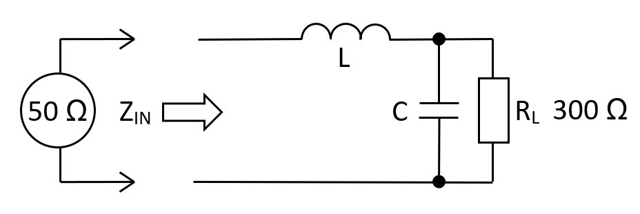
Normal L-Pad circuit
Relevant formulas
$$\boxed{L = R_{IN}\cdot R_L\cdot C}\hspace{0.3cm}\text{and}\hspace{0.3cm}\boxed{C = \dfrac{1}{\omega R_L}\sqrt{\frac{R_L}{R_{IN}}-1}}$$
| RIN: |
|
Ω |
| RL: |
|
Ω |
| FIN: |
|
MHz |
| L: | µH | |
| C: | pF | |
|
Fn:
Natural resonant frequency of the circuit
|
MHz | |
|
AV at FIN:
Voltage gain from \(Z_{IN}\) to \(R_L\)
|
V/V |
Values for L and C
The formulas are found by examining \(Z_{IN}\) and finding the frequency (\(\omega_r\)) where it's resistive \((R_{IN})\). We then move on to calculate \(L\) in terms of \(R_{IN}, C\) and \(R_L\). The input impedance \(Z_{IN}\) is: -
$$\hspace{1.3cm}Z_{IN} = j\omega L + \dfrac{\dfrac{R_L}{j\omega C}}{R_L + \dfrac{1}{j\omega C}} = j\omega L +\dfrac{R_L}{1 + j\omega R_L C} = j\omega L +\dfrac{R_L}{1+\omega^2R_L^2C^2} - \dfrac{j\omega R_L^2C}{1+\omega^2R_L^2C^2}$$
With imaginary terms at zero we can say: \(R_{IN} = \dfrac{R_L}{1+\omega_r^2R_L^2C^2}\). This gives us the value for \(C\): - $$\color{green}{\boxed{C = \dfrac{1}{\omega_rR_L}\cdot\sqrt{\dfrac{R_L}{R_{IN}}-1}}}$$ And we can equate imaginary terms to zero to locate \(L\): - $$\color{red}{\boxed{L = \dfrac{R_L^2C}{1+\omega_r^2R_L^2C^2}}}$$ We can use \(\omega_r^2\) from the green boxed \(C\) formula to further reduce \(L\): - $$\color{red}{\boxed{L =\dfrac{R_L^2C}{1 + \dfrac{R_L}{R_{IN}}-1}=R_{IN}R_LC}}$$
Gain at the operating frequency
To calculate the gain at \(F_{IN}\), use the 2nd order low-pass filter transfer formula. Recognize that \(\omega_n\) (natural resonant frequency) and \(\zeta\) (parallel damping ratio) formulas are involved: -
\(\hspace{0.5cm}|H(j\omega)| = \dfrac{1}{\sqrt{1 +\dfrac{\omega^2}{\omega_n^2}\cdot(4\zeta^2-2) +\dfrac{\omega^4}{\omega_n^4}}}\) \(\hspace{0.25cm}\) where \(\omega_n^2 = \dfrac{1}{LC}\) and, \(\hspace{0.25cm}\zeta = \dfrac{1}{2R_L}\cdot\sqrt{\dfrac{L}{C}}\hspace{0.5cm}\)
Because we know this from earlier: \(\hspace{0.5cm}\color{red}{\omega = \sqrt{\dfrac{1}{LC} - \dfrac{1}{R_L^2 C^2}}}\hspace{0.5cm}\) we can say this: -
\(\dfrac{\omega^2}{\omega_n^2} = \left(\dfrac{1}{LC} - \dfrac{1}{R_L^2 C^2}\right)\cdot LC\hspace{0.25cm}= \hspace{0.25cm}1- \dfrac{L}{R_L^2C}\)
From above \(\dfrac{L}{R_L^2C} = 4\zeta^2\) hence: -
\(|H(j\omega)| = \dfrac{1}{\sqrt{1 +(1-4\zeta^2)\cdot(4\zeta^2-2) +(1-4\zeta^2)^2}}\)
\(|H(j\omega)| = \dfrac{1}{\sqrt{1 +(4\zeta^2 - 2 - 16\zeta^4 + 8\zeta^2) +(1-8\zeta^2+16\zeta^4)}}\)
\(|H(j\omega)| = \dfrac{1}{\sqrt{4\zeta^2}} = \dfrac{1}{2\zeta} = Q\)
This is an interesting result; the gain at \(F_{IN}\) equals the quality factor of the \(R_LLC\) circuit. The only other point that this happens is at \(F_n\) but then, the input impedance isn't resistive.
Apart from the losses in the source's series output resistance, the power transferred is 100%. Using the default example of 50 Ω and 300 Ω, the voltage gain is 2.44949 so, if the source voltage is 1 volt, the actual input voltage to the inductor will be 0.5 volts at 10.000 MHz.
This means the voltage across the 300 Ω load is 1.224745 volts. This is a power of 5 mW. The power into the inductor is 0.5 volts into 50 Ω and that is also a power of 5 mW.