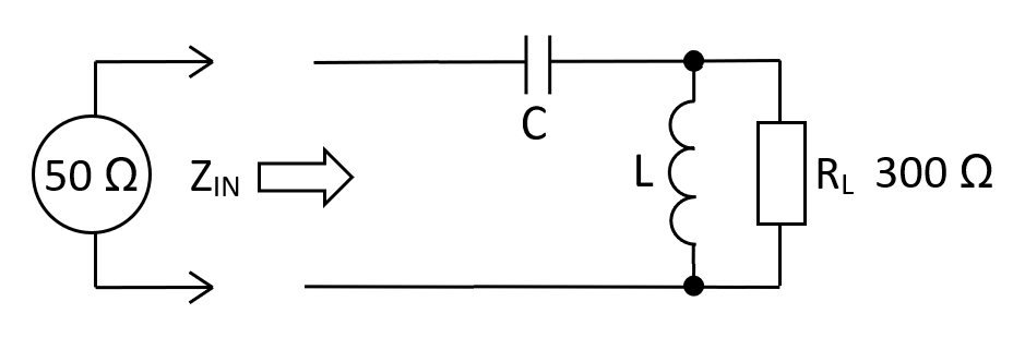
At 10 MHz, a 50 Ω source driving a 300 Ω load via a high-pass L-pad transformer requires a capacitance of 142.35 pF and an inductance of 2.135 μH. Previously it was shown that using the lossy resistive impedance transformer, the attenuation would be 5.63 dB into a 300 Ω.
$$\hspace{0.3cm}\boxed{L = R_{IN}\cdot R_L\cdot C}\hspace{0.3cm}\text{and}\hspace{0.3cm}\boxed{C = \dfrac{1}{\omega R_{IN}}{\sqrt{\dfrac{1}{\frac{R_L}{R_{IN}}-1}}}}$$
| RIN: |
|
Ω |
| RL: |
|
Ω |
| FIN: |
|
MHz |
| L: | µH | |
| C: | pF | |
|
Fn:
Natural resonant frequency of the circuit
|
MHz | |
|
AV at FIN:
Voltage gain from \(Z_{IN}\) to \(R_L\)
|
V/V |
Values for L and C
The calculator formulas are found by examining \(Z_{IN}\) and locating the frequency where this value is purely resistive \((R_{IN})\). We then move on to calculate \(L\) in terms of \(R_{IN}, C\) and \(R_L\). The input impedance \(Z_{IN}\) is: -
$$\hspace{1.3cm}Z_{IN} = \dfrac{1}{j\omega C} + \dfrac{j\omega L\cdot R_L}{R_L + j\omega L} = \dfrac{\dfrac{R_L+j\omega L}{j\omega C}+j\omega LR_L}{R_L+j\omega L} = \dfrac{R_L+j\omega L - \omega^2 R_LLC}{j\omega R_LC - \omega^2LC}\hspace{1.3cm}$$
Next, multiply the numerator and denominator by the denominator's complex conjugate: -
$$Z_{IN} = \dfrac{(R_L+j\omega L - \omega^2 R_LLC)\cdot(-j\omega R_LC-\omega^2LC)}{(j\omega R_LC-\omega^2LC)\cdot(-j\omega R_LC-\omega^2LC)}$$
$$Z_{IN} = \dfrac{-j\omega R_L^2 C +\omega^2R_LLC+j\omega^3R_L^2LC^2 - \omega^2R_LLC-j\omega^3L^2C+\omega^4R_LL^2C^2}{\omega^2R_L^2C^2 + \omega^4L^2C^2}$$
$$\boxed{\hspace{0.5cm}Z_{IN} = \dfrac{-j\omega R_L^2C +j\omega^3R_L^2LC^2 - j\omega^3L^2C+\omega^4R_LL^2C^2}{\omega^2R_L^2C^2 + \omega^4L^2C^2}\hspace{0.5cm}}$$
To find \(\color{red}{\boxed{\omega}}\) that produces a real impedance, equate the numerator's imaginary terms to zero: - $$-\omega R_L^2C + \omega^3R_L^2LC^2 - \omega^3L^2C = 0$$
$$\color{red}{\boxed{\hspace{0.5cm}\omega = \sqrt{\dfrac{R_L^2 C}{R_L^2LC^2-L^2C}} = \sqrt{\dfrac{1}{LC - \frac{L^2}{R_L^2}}}\hspace{0.5cm}}}$$
The value of \(\color{red}{\boxed{\omega}}\) is the operating frequency of the impedance transformer. We use this below: -
But first, with imaginary terms at zero, \(Z_{IN}\rightarrow R_{IN}\) hence: -
$$\boxed{\hspace{0.5cm}R_{IN} = \dfrac{\omega^4R_LL^2C^2}{\omega^2R_L^2C^2+\omega^4L^2C^2}\hspace{0.5cm}} = \dfrac{\omega^2R_LL^2}{R_L^2 + \omega^2 L^2}$$
If we substitute the formula for \(\color{red}{\boxed{\omega}}\) in the above equation, we can drill down to this: -
$$\boxed{R_{IN} = \dfrac{L}{R_L C}} \text{ and therefore } \boxed{L = R_{IN} R_L C}$$
We can now substitute for L in the \(\color{red}{\boxed{\omega}}\) equation hence: -
$$\color{red}{\omega = \sqrt{\dfrac{1}{LC-\frac{L^2}{R_L^2}}}}\color{black}{\Longrightarrow\dfrac{1}{C}\sqrt{\dfrac{1}{R_{IN} R_L-R_{IN}^2}} = \dfrac{1}{R_{IN} C}\sqrt{\dfrac{1}{\frac{R_L}{R_{IN}}-1}}}$$
We can now solve for C: -
$$\boxed{\hspace{0.5cm} C = \dfrac{1}{\omega R_{IN}}\cdot{\sqrt{\dfrac{1}{\frac{R_L}{R_{IN}}-1}}}\hspace{0.5cm}}$$
Gain at the operating frequency
The gain at \(F_{IN}\) is exactly the same as the low-pass L-Pad impedance matching circuit.
Low-pass gain magnitude: -
\(|H(j\omega)| = \dfrac{1}{\sqrt{1 +\dfrac{\omega^2}{\omega_n^2}\cdot(4\zeta^2-2) +\dfrac{\omega^4}{\omega_n^4}}}\)
High-pass gain magnitude: -
\(|H(j\omega)| = \dfrac{1}{\sqrt{1 +\dfrac{\omega_n^2}{\omega^2}\cdot(4\zeta^2-2) +\dfrac{\omega_n^4}{\omega^4}}}\)
Notice that the only difference between low-pass and high-pass is the ratio of \(\omega\) to \(\omega_n\). If you work through the formulas for \(\omega\) for each and did the substitution into the above |H(\(j\omega\))| formulas, the gains are identical.